еә”з”ЁдәҺ77/79 GHzжұҪиҪҰйҳІж’һйӣ·иҫҫзҡ„й«ҳеҸҜйқ жҖ§жқҝжқҗ
е…ій”®иҜҚ: ADAS,иҒҡеӣӣж°ҹд№ҷзғҜ, ж— зҺ»зәӨ, й“ңз®”, жҸ’жҚҹ
ж‘ҳиҰҒ
еҹәдәҺADAS (й«ҳзә§й©ҫ驶иҫ…еҠ©зі»з»ҹ)зі»з»ҹдёӯ77/79GHzжұҪиҪҰйҳІж’һйӣ·иҫҫзҡ„жҪңеңЁеўһй•ҝгҖӮд»Һз”өж°”е’ҢеҸҜйқ жҖ§зҡ„и§’еәҰжқҘзңӢпјҢж— зҺ»зәӨзҡ„иҒҡеӣӣж°ҹд№ҷзғҜйҷ¶з“·жқҝжқҗзӣёиҫғдәҺйқһиҒҡеӣӣж°ҹд№ҷзғҜзҡ„жқҝжқҗе…·жңүжҳҺжҳҫзҡ„дјҳеҠҝгҖӮ
иҒҡеӣӣж°ҹд№ҷзғҜпјҲPTFEпјүзҡ„д»Ӣз”өеёёж•°е’ҢжҚҹиҖ—еӣ еӯҗеңЁдј ж„ҹеҷЁи°җжҢҜйў‘зҺҮиҰҒжұӮзҡ„е·ҘдҪңжё©еәҰиҢғеӣҙеҶ…иЎЁзҺ°еҮәй«ҳзЁіе®ҡжҖ§пјҢеҮ еҚҒе№ҙжқҘеҫ—еҲ°дәҶе°„йў‘е’Ңеҫ®жіўиЎҢдёҡзҡ„е№ҝжіӣи®ӨеҸҜгҖӮ
иҒҡеӣӣж°ҹд№ҷзғҜеҹәжқҗдёҠжҗӯй…ҚжһҒдҪҺзІ—зіҷеәҰпјҲULPпјҢUltra Low Profileпјүзҡ„з”өи§Јй“ңз®”пјҢзӣёиҫғдәҺеҺӢ延й“ңз®”пјҢе…¶жҸ’жҚҹжӣҙдҪҺпјҢжҲҗжң¬д№ҹжӣҙжңүз«һдәүеҠӣгҖӮ
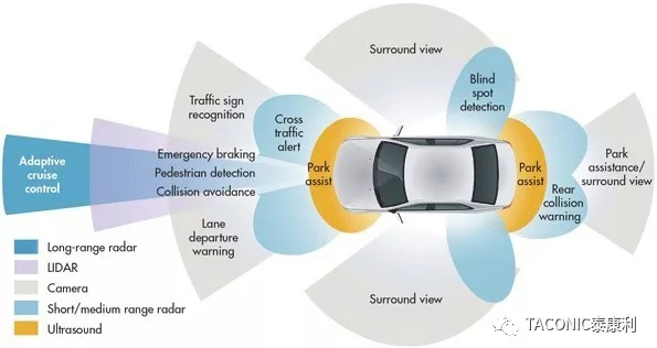
еӣҫ1пјҡADASзҡ„еә”з”Ё
ADAS жЎҲдҫӢ
дёәд»Җд№ҲзҺ°еңЁжҲ‘们йғҪеҜ№ADASзі»з»ҹдёӯзҡ„77/79GHzжұҪиҪҰйҳІж’һйӣ·иҫҫдә§е“ҒеҰӮжӯӨж„ҹе…ҙи¶Је‘ўпјҹе°Ҫз®ЎеүҚжңҹж•°йҮҸдёҚеӨҡпјҢдҪҶеёӮеңәзҡ„еҸҜжҺҘеҸ—еәҰжӯЈеҸҳеҫ—и¶ҠжқҘи¶Ҡй«ҳпјҢе°ұеғҸеҫҲеӨҡе№ҙеүҚзҡ„ABSзі»з»ҹдёҖж ·пјҢд»ҺејҖе§ӢеҸӘжңүиұӘеҚҺиҪҰй…ҚзҪ®еҲ°еҗҺжқҘзҡ„жүҖжңүиҪҰиҫҶй…ҚзҪ®пјҢеҸҜйў„и§ҒжңӘжқҘеҮ е№ҙе…¶е°Ҷе‘ҲжҢҮж•°зә§еўһй•ҝпјҢеӣ дёәжүҖжңүзҡ„жұҪиҪҰеҲ¶йҖ е•ҶйғҪеёҢжңӣеј•е…ҘADASзі»з»ҹгҖӮ
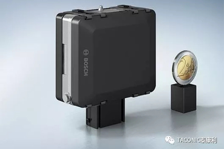
еӣҫ2пјҡ77GHz йҳІж’һйӣ·иҫҫпјҲеҚҡдё–жҸҗдҫӣпјү
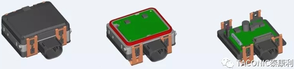
еӣҫ3пјҡ77GHz йҳІж’һйӣ·иҫҫпјҲеҚҡдё–жҸҗдҫӣпјү
жқҗж–ҷзү№жҖ§
PCBдёӯдҪҝз”Ёзҡ„е°„йў‘жқҝжқҗеҝ…йЎ»еңЁйқһеёёе®Ҫзҡ„жё©еәҰиҢғеӣҙеҶ…дҝқжҢҒйқһеёёзЁіе®ҡзҡ„з”өж°”жҖ§иғҪгҖӮPTFEжқҝжқҗжҳҫзӨәеҮәйқһеёёзЁіе®ҡзҡ„DK / DK(@23C)жҜ”еҖјпјҢжё©еәҰз”ұ-50еҲ°+ 150°C(еӣҫ4):
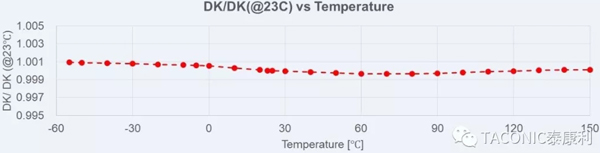
еӣҫ4пјҡPTFEжқҝжқҗд»Һ-50еҲ°+150 °CиЎЁзҺ°еҮәйқһеёёзЁіе®ҡзҡ„Dkзү№жҖ§
еҗҢж ·зҡ„пјҢDfеңЁеҗҢж ·зҡ„жё©еәҰиҢғеӣҙеҶ…зҡ„еҸҳеҢ–йқһеёёе№ізј“(еӣҫ5):
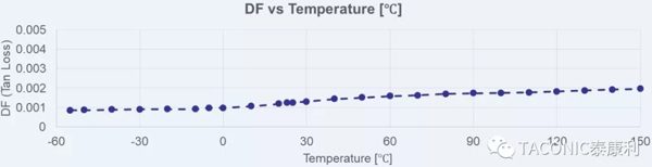
еӣҫ5пјҡPTFEжқҝжқҗд»Һ-50 еҲ°+150 °Cзҡ„Df
иҖҢйқһиҒҡеӣӣж°ҹд№ҷзғҜпјҲNon-PTFEпјүж ‘и„ӮжңүзқҖиҫғй«ҳзҡ„жһҒжҖ§,зўі-ж°§й”®(C-O)е®№жҳ“иў«жһҒеҢ–пјҢе…¶иЎЁзҺ°дёәеңЁй«ҳйў‘еә”з”Ёж—¶з”өж°”жҖ§иғҪдёҚзЁіе®ҡгҖӮ
NF-30жҳҜдёҖж¬ҫдёҚеҗ«зҺ»зәӨзҡ„иҒҡеӣӣж°ҹд№ҷзғҜжқҝжқҗпјҢе…¶еңЁXпјҢYпјҢZдёүдёӘж–№еҗ‘дёҠзҡ„еҗ„еҗ‘дёҖиҮҙжҖ§йқһеёёеҘҪгҖӮд»Һз”өж°”жҖ§иғҪдёҠиҖғйҮҸпјҢ常规зҺ»з’ғзәӨз»ҙеёғзҡ„еӯҳеңЁдјҡеҜјиҮҙжқҝжқҗеңЁеҗ„еҗ‘д№Ӣй—ҙзҡ„е·®ејӮгҖӮеҪ“然жүҒе№ізҺ»з’ғеёғдјҡиҫғ常规зҺ»з’ғеёғжңүдёҖе®ҡж”№е–„пјҢдҪҶд№ҹдёҚиғҪе®Ңе…Ёж¶ҲйҷӨиҝҷдёӘе·®ејӮгҖӮ
“жһҒдҪҺзІ—зіҷеәҰ”з”өи§Јй“ңз®”пјҲULPпјүдёҺдј з»ҹзҡ„дҪҺзІ—зіҷеәҰз”өи§Јй“ңз®”пјҲVLPпјүзӣёжҜ”(еӣҫ6)пјҢULPй“ңз®”иғҪеӨҹеҒҡеҮәжӣҙзІҫз»Ҷзҡ„еӣҫеҪўе’ҢжӣҙдёҘзҡ„зәҝе®Ҫе…¬е·®гҖӮ

еӣҫ6пјҡ ULPHй“ңз®”дёҺVLPй“ңз®”зҡ„еҜ№жҜ”пјҲеҚўжЈ®е Ўй“ңз®”жҸҗдҫӣпјү
жӣҙйҮҚиҰҒзҡ„жҳҜпјҢжҸ’жҚҹеҫ—еҲ°дәҶжһҒеӨ§зҡ„ж”№е–„пјҢйў‘зҺҮи¶Ҡй«ҳи¶ҠжҳҺжҳҫ(еӣҫ7.):
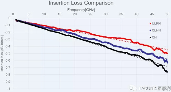
еӣҫ7пјҡNF-30 Hozй“ңз®”зҡ„жһҒдҪҺзІ—зіҷеәҰпјҲULPHпјүпјҢеҸҚиҪ¬й“ңпјҲCLHпјүдёҺдҪҺзІ—зіҷеәҰпјҲCHпјүзҡ„жҸ’жҚҹеҜ№жҜ”
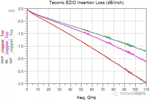
еӣҫ8пјҡ1OZй“ңз®”зҡ„жһҒдҪҺзІ—зіҷеәҰпјҲULPHпјүпјҢеҺӢ延пјҲRAпјүдёҺдҪҺзІ—зіҷеәҰпјҲHVLPпјүжҗӯй…ҚзӣёеҗҢзҡ„д»ӢиҙЁжқҗж–ҷпјҢжөӢиҜ•иҮі110GHzзҡ„жҸ’жҚҹеҜ№жҜ”
1ozзҡ„жһҒдҪҺзІ—зіҷеәҰз”өи§Јй“ңпјҲULPпјүгҖҒеҺӢ延й“ңпјҲRAпјүгҖҒдҪҺзІ—зіҷеәҰз”өи§Јй“ңпјҲHVLPпјүжҸ’жҚҹзҡ„еҜ№жҜ”гҖӮйў‘зҺҮжөӢиҮі110GHzж—¶пјҢULPдёҺRAй“ңзӣёжҜ”пјҢдјҳеҠҝи¶ҠжқҘи¶ҠеӨ§(еӣҫ8).
жӯӨеӨ–пјҢPTFEжқҝжқҗзҡ„еҸҰдёҖдёӘдё»иҰҒдјҳзӮ№еңЁдәҺж— и®әйҮҮз”ЁдҪ•з§ҚиЎЁйқўеӨ„зҗҶж–№ејҸпјҢе…¶й“ңз®”йҷ„зқҖеҠӣеңЁеӨҡж¬Ўж— й“…еӣһжөҒеҗҺпјҢд»Қ然иғҪеӨҹдҝқжҢҒиҫғй«ҳзҡ„ж°ҙе№ігҖӮULPеүҘзҰ»ејәеәҰзҡ„жөӢиҜ•з»“жһңдёҺHVLPеҮ д№ҺдёҖж ·(еӣҫ9).

еӣҫ9пјҡHozжһҒдҪҺзІ—зіҷеәҰпјҲULPHпјүзҡ„й“ңз®”з»ҸиҝҮ3ж¬ЎдёҺ5ж¬ЎIR-ReflowеҗҺзҡ„еүҘзҰ»ејәеәҰ
DKпјҢжҸ’жҚҹзҡ„жөӢйҮҸ
еҶҚеҘҪзҡ„зҗҶи®әж•°жҚ®,дёҚеҰӮеңЁ77GHzжөӢйҮҸе®һйҷ…зҡ„DKе’ҢжҸ’жҚҹгҖӮDKжөӢйҮҸйҮҮз”ЁжіўеҜјиҝһжҺҘеҷЁи°җжҢҜзҺҜжөӢиҜ•ж–№жі•жөӢйҮҸеҫ®еёҰзәҝ,иҖҢжҸ’жҚҹжөӢйҮҸйҮҮз”ЁдёҚеҗҢй•ҝеәҰзҡ„еҫ®еёҰзәҝгҖӮ(еӣҫ10).
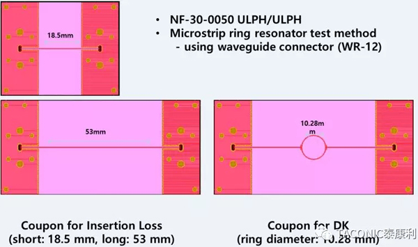
еӣҫ10пјҡDkдёҺжҸ’жҚҹзҡ„еҫ®еёҰзәҝи°җжҢҜзҺҜжөӢиҜ•еӣҫеҪў
еңЁ77GHzжөӢиҜ•йў‘зҺҮдёӢпјҢULPй“ңз®”ж”№е–„дәҶжҸ’жҚҹпјҢдҪҶжҳҜDKжҜ”жҷ®йҖҡй“ңз®”еңЁ77GHzж—¶зҡ„зҗҶи®әеҖјдҪҺдәҶеӨ§зәҰ0.1 (еӣҫ11).
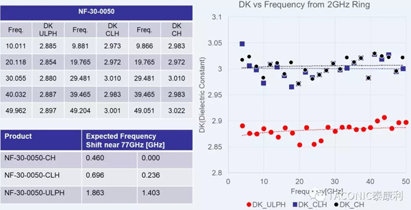
еӣҫ11пјҡNF-30 DkйҡҸйў‘зҺҮзҡ„еҒҸ移дёҺй“ңз®”зұ»еһӢжңүе…і
иҝҷз§ҚеҪұе“ҚжҳҜз”ұдәҺиҝҷз§Қй“ңз®”зҡ„зұ»еһӢеҜјиҮҙзҡ„пјҢдҪҶеҫҲе®№жҳ“еңЁд»ҝзңҹиҪҜ件йҮҢиҝӣиЎҢи°ғж•ҙгҖӮ
и°җжҢҜзҺҜS21еңЁ-40°C е’Ң+125°CжөӢйҮҸиЎЁзҺ°дәҶиҝҷдёҖзӮ№еҒҸ移(еӣҫ12):
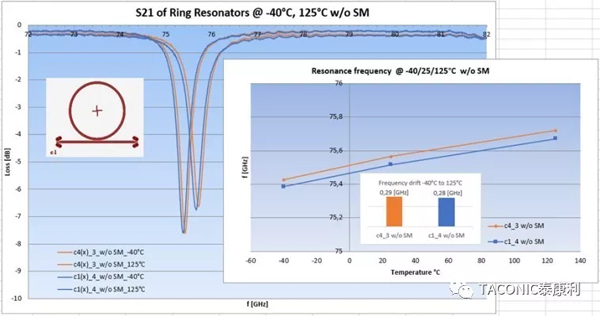
еӣҫ12пјҡS21и°җжҢҜзҺҜжөӢйҮҸзҡ„еңЁ-40°Cе’Ң+125°CеҒҸ移пјҲеҚҡдё–жҸҗдҫӣпјү
еҗҢж—¶и°җжҢҜзҺҜеңЁ78~80GHzзҡ„жҸ’е…ҘжҚҹиҖ—д№ҹжҳҜеҸҜд»ҘжҺҘеҸ—зҡ„(еӣҫ13):

еӣҫ13пјҡS21и°җжҢҜзҺҜеңЁ-40°C е’Ң+125°CжөӢйҮҸзҡ„жҸ’жҚҹпјҲеҚҡдё–жҸҗдҫӣпјү
еӨ§еӨҡж•°зҡ„77/79 GHz ADAS зәҝи·ҜжқҝжҳҜеӨҡеұӮж··еҺӢжқҝ, еҸӘжңү第1еұӮеҲ°з¬¬2еұӮжҳҜPTFEжқҝжқҗ.
PTFEжқҝжқҗзҡ„й«ҳеҸҜйқ жҖ§еңЁд»ҘдёӢзҡ„288 °Cзҡ„жјӮй”ЎжөӢиҜ•дёӯеҫ—еҲ°йӘҢиҜҒ(еӣҫ14 a-c):
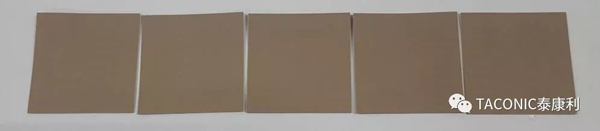
еӣҫ14a: NF-30 288°CжјӮй”ЎеүҚ
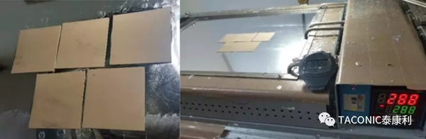
еӣҫ14b: NF-30 еңЁеҒҡ288 °CжјӮй”Ў

еӣҫ14c: NF-30 288 °CжјӮй”Ў30еҲҶй’ҹеҗҺ: жІЎжңүиө·жіЎпјҢжІЎжңүзҲҶжқҝ!
дҪҝз”ЁиҫғеҺҡзҡ„еҺҡеәҰ20е’Ң60milзҡ„NF-30жқҘжөӢиҜ•й’»еӯ”пјҢйҷӨеӯ”жұЎе’Ңз”өй•Җеӯ”пјҢеҫҲжҳҺжҳҫиҝҷз§Қж— зҺ»зәӨPTFEжқҝжқҗPTHеӯ”еӯ”еЈҒиҙЁйҮҸйқһеёёй«ҳ(еӣҫ15)
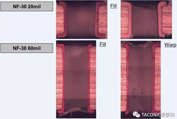
еӣҫ15: 20milдёҺ60mil NF-30зҡ„PTHеӯ”
1000ж¬Ў-40°CеҲ°+ 140°CеҶ·зғӯеҶІеҮ»еҫӘзҺҜжҳҜеҜ№ж··еҺӢеӨҡеұӮжқҝжқҘиҜҙжҳҜжһҒеӨ§зҡ„жҢ‘жҲҳ(еӣҫ16, 17)
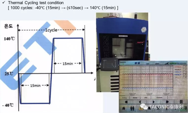
еӣҫ16: ж··еҺӢеӨҡеұӮжқҝзҡ„еҶ·зғӯеҫӘзҺҜжӣІзәҝ -40°CеҲ°+ 140°C 1,000еҫӘзҺҜ
дёҚз®ЎжҖҺж ·пјҢ1000ж¬ЎеҫӘзҺҜжөӢиҜ•еҗҺжІЎжңүд»»дҪ•й—®йўҳгҖӮ
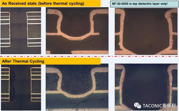
еӣҫ17пјҡNF-30ж··еҺӢеӨҡеұӮжқҝеҲҮзүҮ –NF-30зҡ„еӨҡеұӮжқҝеҸҠзӣІеӯ”пјӣзғӯеҫӘзҺҜеүҚдёҺзғӯеҫӘзҺҜеҗҺ
еҚідҪҝз»ҸиҝҮ50ж¬Ўзҡ„жјӮй”ЎиҜ•йӘҢ(288 °CпјҢ10S)пјҢдҫқ然жҳҫзӨәеҮәеҫҲй«ҳзҡ„еҸҜйқ жҖ§(еӣҫ18)
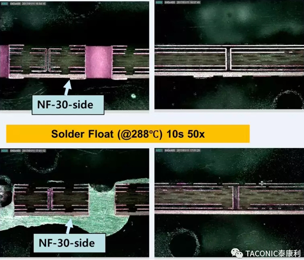
еӣҫ18пјҡNF-30зҡ„ж··еҺӢеӨҡеұӮжқҝз»ҸиҝҮ50ж¬ЎжјӮй”Ў( 288 °C 10з§’)
й«ҳеҸҜйқ жҖ§е’Ңз”өж°”жҖ§иғҪйңҖиҰҒд»Һжқҝжқҗзҡ„з”ҹдә§иҝҮзЁӢеҲ°еңәжҷҜеә”з”ЁдёҖзӣҙдҝқжҢҒзқҖзЁіе®ҡзҡ„д»Ӣз”өеёёж•°гҖӮдёҖдёӘдј—жүҖе‘ЁзҹҘзҡ„йЎҫиҷ‘е°ұжҳҜйҷ¶з“·еЎ«ж–ҷжқҝеңЁPCBеҲ¶дҪңиҝҮзЁӢдёӯзҡ„иҚҜж°ҙеҗёйҷ„й—®йўҳгҖӮNF-30йҮҮз”ЁжӣҙеҘҪзҡ„й…Қж–№жқҘеҮҸе°‘жңҖеёёи§Ғзҡ„еҢ–еӯҰиҚҜж°ҙзҡ„жё—йҖҸй—®йўҳгҖӮ еӣҫ19жҳҫзӨәдәҶNF-30дёҺеёӮеңәзҡ„еҸҰдёҖж¬ҫж— зҺ»зәӨз»“жһ„PTFEд»ӢиҙЁжқҗж–ҷзҡ„иҖҗеҢ–еӯҰиҚҜж°ҙеҗёйҷ„жөӢиҜ•з»“жһңгҖӮ
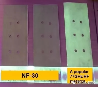
еӣҫ19:NF-30дёҺе…¶д»–жқҗж–ҷзӣёжҜ”пјҢжҳҺжҳҫеҮҸе°‘еҢ–еӯҰиҚҜж°ҙзҡ„еҗёж”¶
з»“и®ә
NF-30 жҳҜдёҖж¬ҫй«ҳеҸҜйқ жҖ§е°„йў‘жқҗж–ҷпјҢйҖӮз”ЁдәҺ77/79GHz жұҪиҪҰйҳІж’һйӣ·иҫҫзҡ„ж··еҺӢеӨҡеұӮжқҝ, зәҜеӨҡеұӮжқҝд»ҘеҸҠеҸҢйқўжқҝзҡ„и®ҫи®ЎгҖӮ
еҸӮиҖғж–ҮзҢ®
йҷӨдәҶдёҖдәӣзү№е®ҡзҡ„еј•з”ЁеӨ–пјҢе…¶д»–жүҖжңүдҝЎжҒҜйғҪжҳҜTaconicеҶ…йғЁжөӢиҜ•дҝЎжҒҜгҖӮ
———————————————————
йҷ„иӢұиҜӯеҺҹж–Үпјҡ
FOR 77/79 GHZ SAFETY AND RELIABILITY APPLICATIONS THE MOST RELIABLE LAMINATES ARE USED
Manfred Huschka1
1Taconic Advanced Dielectric Division,Mullingar, Ireland
Keywords: ADAS, PTFE, NON-REINFORCED,COPPER FOIL, INSERTION LOSS
Abstract
Due to the expected potential growth of 77/79 GHz ADAS (Advanced Ariver-Assistance System) several non-PTFE (Polytetra Fluoro Ethylene) laminates are trying to find their way into designs. However from electrical and mechanical reliability points of view non-reinforced PTFE/Ceramic laminates still provide a leading edge.
The high consistency of dielectric constant and loss factor of the thermoplastic material PTFE over the required operating temperature range at resonance frequency of the sensors has been recognized by the RF and microwave industry since tens of years. This is also one of the main reasons why such types of laminates are being used for every ADAS generation up to now.
For many years only one kind of such laminate was available and therefore is widely used in the industry. 2017 saw the emergence of another such type of laminate, whose tested reliability data confirm that the selection of non-reinforced PTFE laminates for 77/79 GHz is the correct one. In fact, certain features demonstrate a second generation laminate is needed in order to meet the requirements of next generation 77/79 GHz ADAS.
The market introduction of almost no profile ED (Electro-Deposited) copper foil provides an even improved insertion loss over rolled annealed copper foil, in addition to its lower cost. Only PTFE laminates result in high enough copper peel strength even at repeated rework cycles.
The Case for ADAS
Why are we now so interested in 77 GHz ADAS? It has been around for some time, although in small volumes. The market acceptance is becoming quite high, and in a similar way as ABS years ago it gets cascaded down from luxury cars to almost every car. Exponential growth rates in the next few years are expected – and will happen, because all the car makers want to introduce ADAS.
Safety and reliability have become key words in the industry.
BaseMaterial Characteristics
The RF laminate used in the printedcircuit board is required to be very stable over a very wide temperature range.PTFE laminates show a very tight DK/DK(@23C) (Dielectric Constant/Loss Factor) behaviourfrom -50 to +150 °C (Fig. 4):
Likewise the gradient of DF over the same temperature range is very low (Fig. 5):
Non-PTFE organic resins are bound to have higher levels of natural electrical polarity - the Carbon-Fluorine bond in PTFE is short and not very polarizable in an electrical field, while Carbon-Oxygen bonds are naturally more polarizable. This means a lesser degree of stability over frequency.
NF-30 is a non-reinforced PTFE laminate, just containing ceramic fillers. Same as the laminate being used for current 77 GHz designs, it is electrically very homogeneous in all 3 directions. A woven fiberglass reinforced resin will naturally have some electrical anisotropy due to the fiberglass weave structure, which in particular high mmWave frequencies are sensitive to. It is possible to flatten the fiberglass however the warp yarns never get flat. There will always be a higher level of anisotropy in these type of resin systems.
Recent developments in copper foil technology have resulted in the introduction of a so-called “Almost No Profile” ED copper foil [Taconic grade name for Hoz is ULPH] (Fig. 6). Compared with a traditional Very Low Profile copper foil this foil leads to better defined and much steeper sidewalls of traces due to less copper treatment which has to get etched out of the substrate; in other words, finer features with tighter tolerances are possible.
And what’s of significance is that the insertion loss gets improved considerably – the higher the frequency the better the insertion loss (Fig 7.):
Insertion Loss Comparison of 1 oz “Almost No Profile” ED copper foil (ULP), Rolled Annealed copper foil (RA), and Flat Profile ED copper foil (HVLP) on a different substrate, measured up to 110 GHz shows that the improvement gap widens even more compared with RA copper foil (Fig. 8).
A major advantage of a thermoplastic substrate, such as PTFE, lies in the high copper foil peel strength even after repeated IR reflows, irrespective whether an organic surface protection (PSR) is used or just immersion tin. Measured peel strength values are in the same range as of standard Very Low Profile copper foil (Fig. 9).
mmWave Measurements
All theory is fine, however the proof isin the pudding when doing actual DK and Insertion Loss tests at 77 GHz.Microstrip ring resonator test method using waveguide connectors is applied forDK measurements, whereas strip lines of different lengths are used forInsertion Loss (Fig. 10).
Although the Almost No Profile copper foil improves the insertion loss, it also leads to a DK shift to a 0.1 lower value for design purposes at 77 GHz (Fig. 11).
This observed effect is due to the actual profile structure of this copper foil, and can easily be incorporated into any design through simulation software.
S21 of ring resonators measured at -40°C and at +125°C show a quite small frequency drift (Fig. 12):
Also the observed loss in the frequency range between 78 and 80 GHz shows an acceptable increase (Fig. 13):
Most 77/79 GHz ADAS pcbs are hybrid multilayer pcbs, where only layers 1 and 2 are PTFE laminate.
Aforementioned high reliability of PTFE laminates can easily get demonstrated during 288 °C solder float (Fig. 14 a-c):
Taking the unusual step of using rather thick 20 and 60 mil NF-30 to demonstrate via drilling, hole wall desmearing and pth, it is obvious that it is of no issue for this no glass containing PTFE laminate (Fig. 15)
The biggest challenge is thermal cycling of the hybrid multilayer - 1,000 cycles from -40°C to + 140°C (Fig. 16, 17)
Howeverthe hybrid multilayer survives this test without any issues:
And even after 50x solder float (10 s at 288 °C) the hybrid multilayer shows its superior quality (Fig.18)
Reliability and electrical performance needs dielectric consistency from laminate production through to field deployment. A known concern with ceramic filled dielectrics is process chemistry absorption during the PCB fabrication steps. Observations in one popular laminate of cosmetic changes, as well as some measured shifts in electrical properties at 77/79GHz. It is much preferred to have finished PCBs with no contamination and NF-30 is constructed to minimize penetration and interaction of most common PCB chemistry. Fig 19 shows tests of machined NF-30 dielectric. This is achieved through care in ceramic filler selection and mixing, leading to better cosmetic results after etching in the PCB production process.
Conclusion
NF-30 is truly a high reliability RF basematerial, suitable for 77/79 GHz ASAS hybrid multilayer printed circuit boards,all-RF multilayer printed circuit boards, as well as double-sided printedcircuit boards. The combination of non-reinforced PTFE laminates with Almost NoProfile copper foil is the ideal solution – providing the supply chain with asafe knowledge of long term reliability in operation.
References
Except wherespecific references were made all other information is Taconic internal test information.
Biography
Dipl.-Ing. Manfred Huschka spent his entire professional career in the printed circuit board industry: After graduation he was manufacturing printed circuit boards (Braun Ireland Ltd). Thereafter manufacturing FR4 base materials (AlliedSignal Laminate Systems), with his final position being Director Technology Europe. Since 1997 Manfred is with Taconic, manufacturing PTFE base materials. In those more than 20 years he was in charge of the Irish manufacturing plant for more than 10 years, and is Vice President Global Sales.
 зІӨе…¬зҪ‘е®үеӨҮ 44030902003195еҸ·